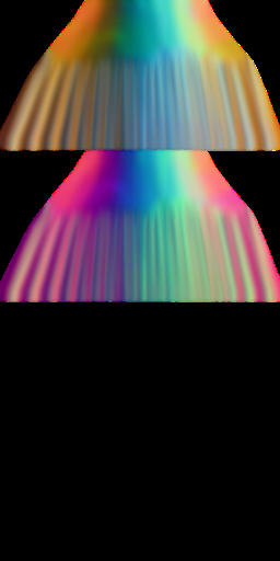
Save the image as a texture by clicking the 'Save image' button (15). Load the XMF into the previewer and apply the texture. You will see this:
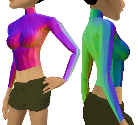
Note that there are no black lines around the seams, so no posterior editing is necessary to erase them.
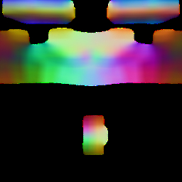
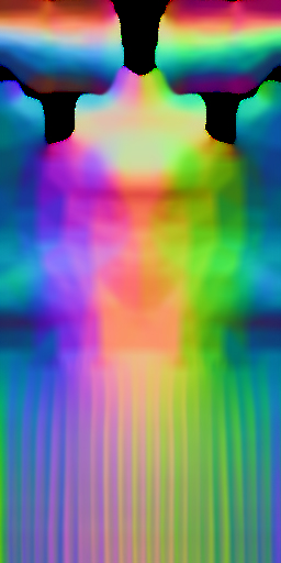
However, each face (triangle) in the mesh has its own colour, which makes the mesh look less smooth. The solution to this is to blur the texture. Take the blur slider (25) and move it across to the right to about half way. You will see the blur effect in real time. If you export the texture and apply it to the mesh in the previewer, you will see a smooth gradation of colours, much like this:
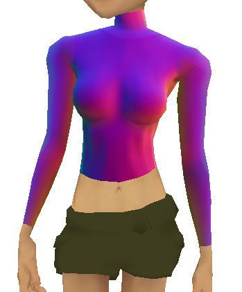
Note the difference between this and the unsmoothed images above.
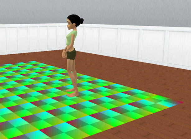
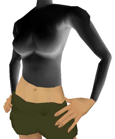
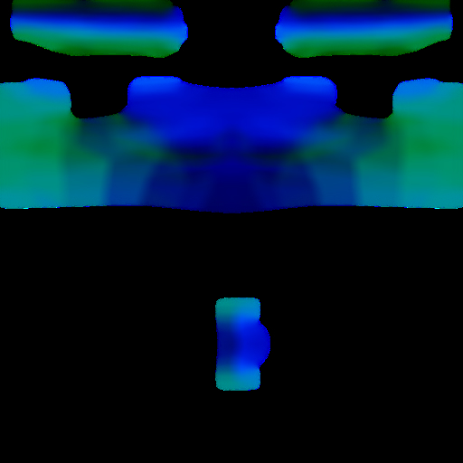
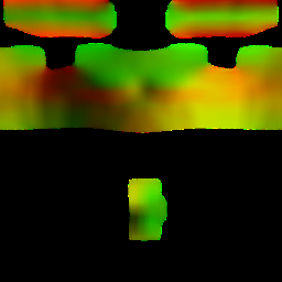
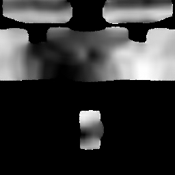
As in this example, the CAST utility creates textures for XMF meshes as if the were illuminated by three lights. A red light shines from the right, a green light shines from behind, and a blue light shines from above. You can change the intensity of these lights by using the R, G and B sliders (buttons 17, 18, and 19). For instance, with G set to to 50%, and R set to 0%, the texture looks like this:
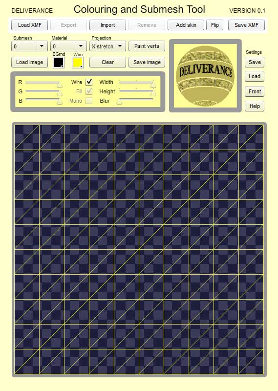
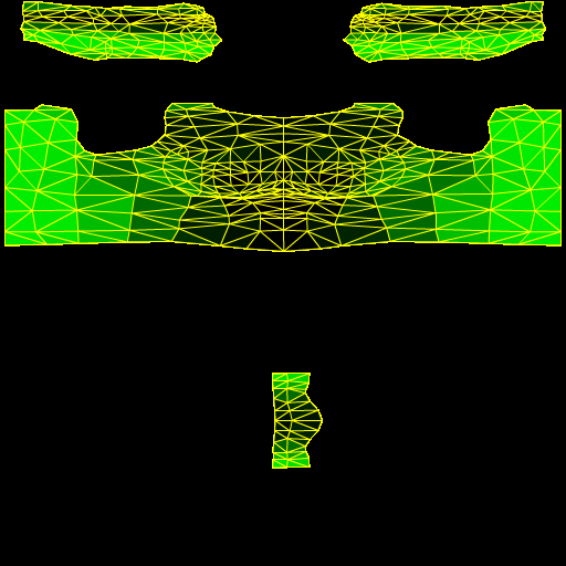
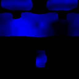
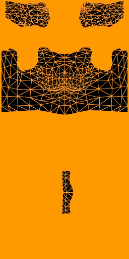
By removing the blur, removing all but green and activating the 'Wire' checkbox (20) , we obtain:
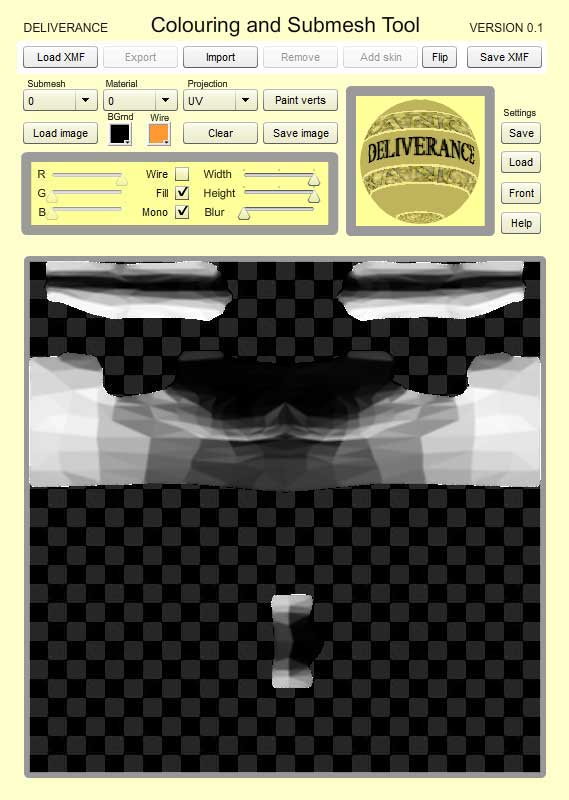
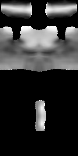
The 'Mono' checkbox (22) produces a texture as if the mesh were lit by a white light from above. Note at this point that the width and height sliders (23 and 24) can be adjusted to produce standard-sized textures:
Not only can you adjust the intensity of the lights, but you can change the directions they shine from. This is done using the 'trackball' (16) which you can roll around with your mouse. The following are example of some lighting effects that can be obtained by adjusting the trackball and other controls:
 |
 |
 |
 |
If you find a setting that you like, click save (26) under 'Settings' on the right. This will allow you to save a little xml file on your computer, so you can use exactly the same lighting conditions for other meshes in the future. Load a previously-saved file by clicking the 'Load' button (27). The button underneath, called 'Front' (28) returns the trackball to its initial position, thus re-setting the light angles.
Mentioned above was the 'Wire' checkbox (20). This can be used with or without the 'Fill' checkbox (21), but you would normally use it without a blur. The wire colour can be changed using the 'Wire' colour-picker (13). You can also change the colour of the background using the BGrnd colour-picker (12), or load a background image using the 'Load image' button (11). These backgrounds can be removed by clicking the 'Clear' button (14):
 |
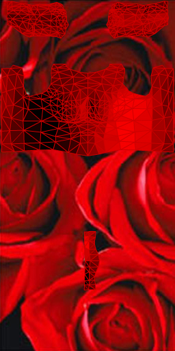 |
The ability to change the background is not just to produce funky-looking UV maps. If you use the blur, slider the background and the filled triangles are blurred together, which is noticeable at the UV seams on the 3D model. Mainly though, the ability to load a background image is for vertex painting, which is discussed below.
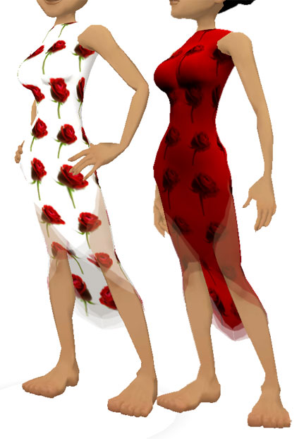
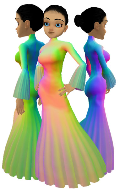
As a final example, here is a dress of mine, with beautiful CAST textures applied to it - and here with 'self-illuminated' activated in the previewer, to hide the normal shadows:
 |
 |
 |
b) VERTEX PAINTING
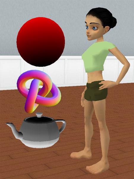
Vertex painting, or vertex shading, refers to the way in which, in IMVU, a vertex can have its own colour – independently of the texture applied to the mesh. Since vertex painting isn't used much, this point is worth stressing: the vertices in a mesh can all have their own colour - regardless of the texture you apply on top. In fact, by default, all the vertices are generally coloured black, but we usually tell the previewer/client to ignore the black, by making sure that the previewer's 'Vertex colors' checkbox is not activated. When the 3 vertices making up each triangle in a mesh are different colours, the inside of the triangle blends between the colours like this:
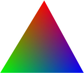
Remember: The colour information is stored in the XMF file itself. When you have a mesh that contains painted vertices, the vertex colour and the texture blend together.
One disadvantage of vertex painting is the resolution. Since all you can specify are the colours of the verts, the resolution of any image is limited by the density of vertices in the mesh. Low-poly meshes -of the type that are better for IMVU- mean low resolution. On the other hand, vertex painting is 'free' (it does not add to the product size), and is great for 'baking in' shadows, giving a colour 'cast' to you mesh, or enhancing or replacing the effects or lighting.
The CAST utility takes a jpg and an XMF. It then looks for the colour of the pixels in the jpg in the place where they appear in the XMF's UV map, and applies that colour to the vertex in the XMF.
To illustrate this I created a plane in 3ds max that had a resolution of 60x60. Of course there is no need whatsoever to use a flat 60x60 plane in IMVU - a 1x1 plane will do just as well (and be lighter on your machine), but for example's sake, I wanted a high-density mesh, with tightly-packed vertices.
I loaded the XMF into the CAST utility. As expected, the utility created a default texture (see 'Create Default Textures', above), but it's a rather boring one, since all the triangles in the plane face the same way, and so are painted the same colour =)
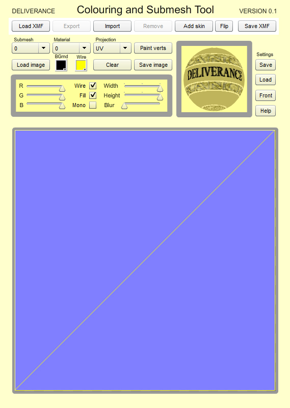
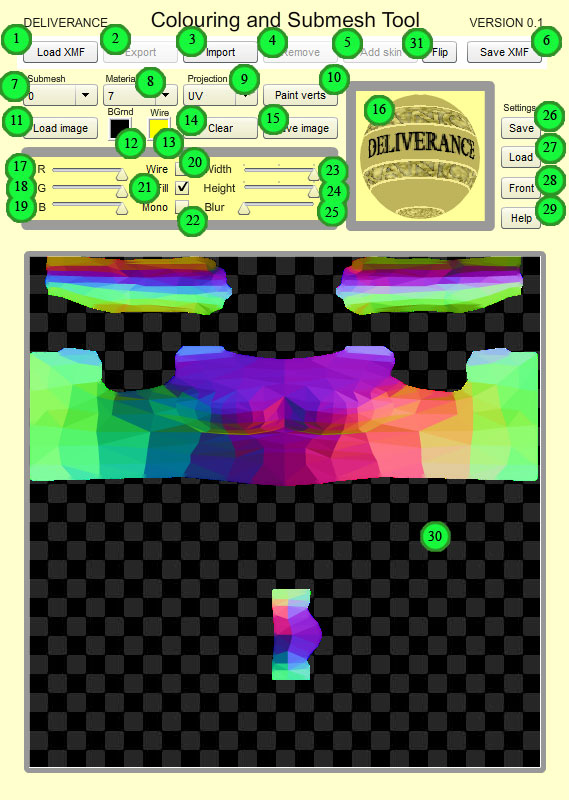
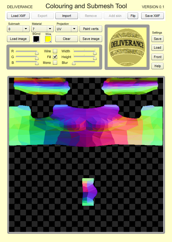
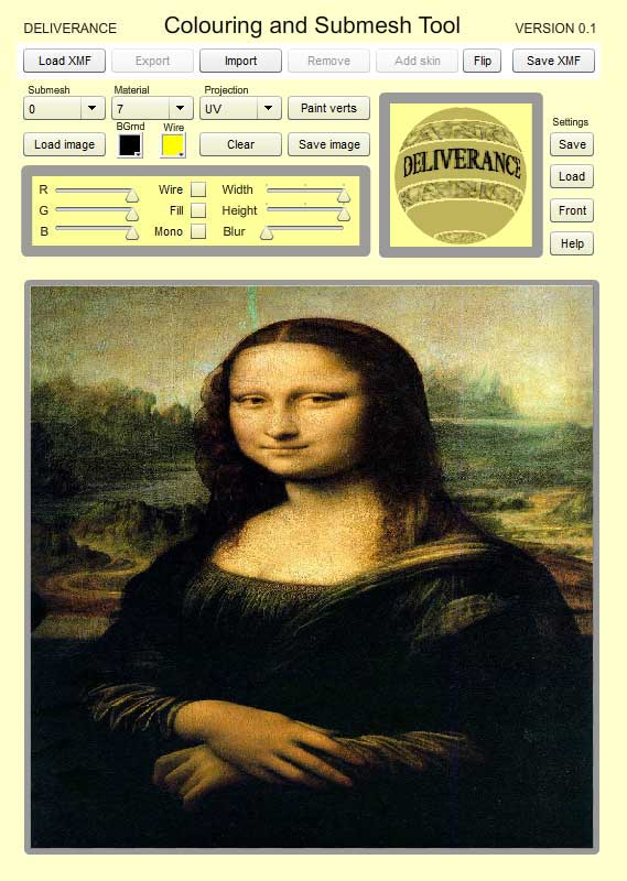
To use the vertex painting, deactivate both the Wire (20) and the Fill (21) checkboxes - so the image area (30) is blank. Click on 'Load image' (11) and load an image. I loaded a picture of the Mona Lisa (all images adjust to fill the available area):
Once the image is loaded, all that remains is to click the 'Paint verts' button (10), and save the updated XMF file, clicking 'Save XMF'(6). On loading the mesh into the previewer, you see this:

Remember the mesh pictured above has only a blank, white texture - the image you see is all done with vertex painting!
The following example is more practical, and shows the effect of combining textures and vertex painting.
I made a series of 5 low-poly columns in 3ds max, each one in its own submesh, but all with identical UV maps and the same material number (which I set to zero).
In the previewer, they look like this:
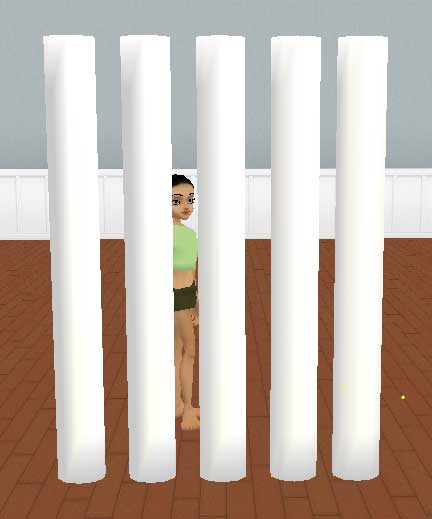
and all have the same UV map:
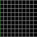
On loading the XMF into the CAST utility the default coloured texture appears for the first submesh:
Notice the sub-mesh drop-down menu (7) which allows you to change between the different submeshes in your XMF.
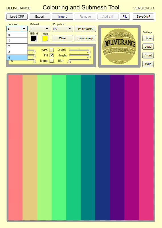
I unclicked the Fill checkbox (21) so that the image area went blank. For the first submesh, I loaded in an image (below), and pressed paint verts. I then did the same for the rest of the submeshes (5 in total), using these images, one for each on my columns:
 |
 |
 |
 |
 |
The idea here is to shade the vertices in the columns to create the appearance of darker columns at one end and lighter columns, as if they were progressively shaded.
I saved the updated XMF, loaded it into the previewer, and activated the Vertex Colors checkbox. The columns now appear with the gradual shading:
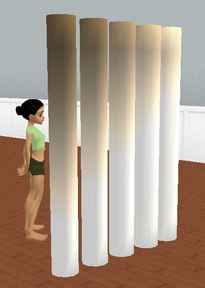
Finally, I applied a simple texture to the mesh, which appears on all the columns (since the UVs and material number is the same on all the columns):
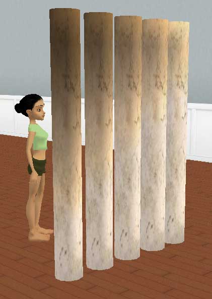
Above, you can see that the texture on all the columns is the same, but they are nonetheless different due to the underlying vertex shading. If someone were to derive from these columns, they could apply a new texture, but the shading would remain (unless they unchecked the Vertex Colors checkbox in the previewer). Note one of the uses of vertex shading here - without vertex painting the only way to create the effect above is to have a different texture on each column. With the vertex painting, all the columns share a single texture.
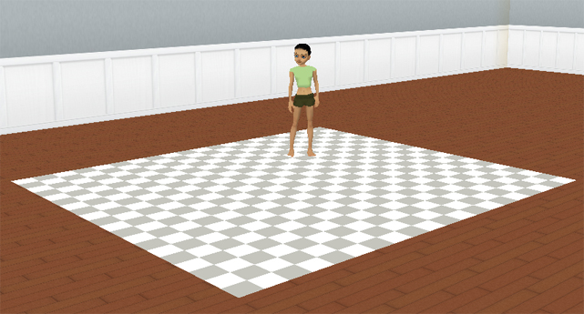
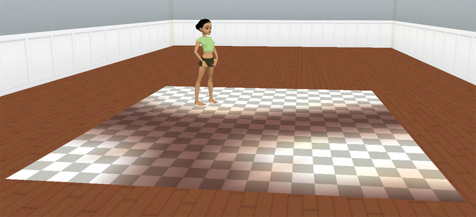
Nonetheless, the mesh I used above contains 5 submeshes - one for each column, and picking a particular submesh enables the utility to vertex-paint that particular submesh only. Consider instead to the example of a simple tiled floor (where all the tiles for part of the a single submesh).
I created a plane of 10 tiles by 10 tiles, and mapped the floor so that all the tiles had the same simple square map. In other words, applying this half-a-K 128x128 pixel texure in the previewer